After relining both brakes and scrapping the badly worn cup-and-cone hub bearings, I decided to unspoke the wheels. In the first place, the rims and outer surfaces of the brake drums were so corroded with rust that it was impossible to prepare them for enamelling while the wheels remained built up. Secondly, the spokes were also eaten up with rust and several were bent.
In the interest of safety it was desirable to renew the spokes and nipples. Before unscrewing the nipples, however, I made a note of the following points as a guide to subsequent rebuilding: a) the pattern of the spoking on both sides of the hub; b) the lateral disposition of the rim relative to the hub, and; c) the gauge – thickness – and exact lengths of the spokes on each side.
Enjoy more Old Bike Mart reading every month.
Click here to subscribe & save.
The man who is confident of his ability, who takes due note of the previously enumerated aspects of wheel spoking and who invokes a specialist’s aid only for final trueing may save himself about 10 shillings a wheel on rebuilding costs as compared with the man who entrusts the complete job to a specialist concern. But it is the experience of such firms that only a small percentage of amateurs succeed in lacing their wheels correctly.
Next job on the hubs, rims and brake plates was the removal of rust and old enamel, followed by preparation and enamelling of the surfaces. However, since the enamelling of these and other components will form the subject of a subsequent article, I will deal with the rebuilding of the hubs, brakes and wheels which was undertaken after the enamelling process.
Each brake plate and hub bore the name Harwil which I recognised as a trade name of the Albion Engineering Co Ltd. Cost of the new spindles, cups, cones and balls for both wheels totalled 19s-6d.
It transpired that the rear hub and spindle of the Calthorpe had previously been replaced by components of OK Supreme pattern in which the distance between the cups was about quarter of an inch greater. The slightly longer OK Supreme type of rear spindle was therefore necessary as a replacement. The incident illustrates the advisability of sending patterns when ordering replacements for an old machine.
Before fitting new cups into hubs one should verify that the housings are clean and free from burrs. In the case of the Calthorpe the cup housings had been smeared with grease during paint spraying; consequently a wipe with an old rag removed both enamel and grease. Slight burrs in the housings were removed with a half-round scraper, after which the bores were cleaned with a well-worn piece of fine emery cloth followed by petrol and clean rag. The cups were then pressed into position with a small hand-press which. Had I lacked the press I would have driven the cups home with a hammer and suitable drift. Whichever method is used it is essential to maintain the cups absolutely square with their housings throughout the procedure; otherwise they may become jammed and damage the housings.
When removing the old cups from the rear hub I had found a one-eighth of an inch thick steel washer behind each cup. The purpose of the washers was apparently to provide a substantial seat for the cups, since the internal shoulder forming the bottom of each housing was of shallow radial depth. By way of confirmation I measured the depth of each housing, which proved to be one-eighth of an inch more than the combined thickness of its cup and dust cover. Accordingly the washers were replaced in the housings before the cups were pressed home.
Assembly of the bearings from that stage onward was straightforward, though one or two points deserve mention. It is essential to lock non-adjustable cones securely on a wheel spindle; this I did by means of my small Stillson wrench. Sometimes it is found that the threaded ends of a spindle are of unequal lengths. In that case the longer end usually belongs on the brake side of the hub, but a check of the thicknesses of all the spindle fittings will soon settle the point. The non-adjustable cone should be fitted to the brake side of the spindle so that it is not necessary to disturb the brake when making bearing adjustments.
High melting point grease was used to pack the bearings during assembly. This type of grease should always be employed for hubs and brakes as general purpose grease, which has a lower melting point, may become fluid under the influence of heat generated in the brake and find its way on to the friction surfaces, rendering the brake useless.
When bearing assembly was completed the dust caps were lightly tapped into position and surplus grease was wiped away.
The brakes were then reassembled. The faces of the cams showed slight traces of wear and were smoothed with a fine file. Cellulose enamel was removed from inside the camshaft bushes with a rag dipped in cellulose thinners. The camshafts, cam faces and shoe pivots were smeared with high melting point grease and the surplus was wiped away after assembly. The cam levers were fitted to their shafts and the brakes tested for smooth, positive operation. The brakes were then slipped on to the wheel spindles and were applied – in order to centralise the shoes in their drums – while the brake plate retaining nuts were tightened.
Spinning the hubs then provided a check of freedom from rubbing of the brakes. The face of the rear drum rubbed the shoe plate once every revolution. A thin washer fitted over the wheel spindle between the shoe plate and the non-adjustable cone cured the trouble. The front brake was perfectly free without the use of any of the three washers which were found between the cone and the shoe plate on dismantling.
Replacement spokes of the correct gauge and lengths, together with nipples, were then obtained and the wheels laced to the pattern and displacement previously noted. Those who undertake the task of wheel lacing for themselves should note that alternate spoke-nipple holes in the rim incline towards opposite sides of the rim. Where there is a difference in the diameters of the two spoke flanges of a hub, a spoke and nipple threaded through one hole in the rim will be tangential to a larger-diameter circle than when inserted in an adjacent hole pointing to the opposite side of the rim. From that observation one can readily decide which side of the rim belongs to which side of the hub. Final truing of the wheel, as previously mentioned, is positively a task for the specialist.
After the Calthorpe wheels had been trued they were fitted with new rim-tapes, tyres and tubes. A 3.25 x 19in studded tyre was chosen for the rear wheel and a 3.00 x 19in ribbed pattern for the front.
With the renovation of the wheels and brakes completed, my next task was to remove the mudguards, tank, handlebar and front fork, then dismantle the bolted-up frame, leaving the sub-assembly of engine and gearbox for attention. Many quarter-inch diameter attachment bolts sheared during dismantling, since their nuts were firmly rusted on their threads. Those which did not shear were so badly eroded that I scrapped them and decided to fit new nuts and bolts when the time came for assembly. The cycle parts were put on one side for subsequent preparation and enamelling.
Before the engine and gearbox could be separated it was necessary to remove the primary chaincase and primary drive. The outer half of the cast aluminium chaincase was too badly smashed for building up by welding to be an economic proposition. Consequently it was taken as a pattern to Abbey Spares Ltd, a south London breaker which was able to supply a serviceable second-hand replacement for 15 shillings.
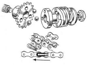
The nut retaining the engine-shaft shock absorber was no more than finger tight. The shock absorber was found to be of a type in which the adjacent faces of the driving and driven members each have three conical depressions radially disposed at 120 degrees to each other. The splined driving member is spring-loaded axially and three large steel balls located in the recesses transmit the drive and, by riding up the conical slopes and forcing the two members apart against spring pressure, absorb transmission shocks.
In the Calthorpe two of the steel balls were missing and shallow annular grooves joining the recesses indicated that overriding had been taking place. (Probably the retaining nut had worked loose during service, allowing overriding with the result that two of the balls had become displaced and had jammed between the engine sprocket and the chaincase, smashing the case.) The maker’s instruction book showed that 7⁄16in diameter balls should be used and hence three new steel balls of that size were obtained.
When removing the primary chain I noticed that the spring clip of the connecting link had been fitted backward. As a safety precaution spring clips should always be fitted with their rounded (closed) ends facing the direction of chain travel. The chain was washed in petrol and checked for backlash. Total backlash was no more than one-eighth of an inch per foot, so the chain was soaked in oil ready for further service. The teeth on the engine and clutch sprockets were examined for wear and found to be quite serviceable. ![]()
(To be continued)